04. Basic Lighting Shader - Part 1

New HLSL in this chapter
- NORMAL: a shader semantic used to retrieve normal data from a vertex buffer
- normalize(): normalizes a vector
- dot(): dot product function
- saturate(): clamps a value to [0, 1] range
- reflect(): vector reflection function
- pow(): raises base to the power of exponent
New math in this chapter
- dot product: can be used to find the cosine value of an angle quickly
- normalization: converts a vector to a unit vector, which has a length of 1
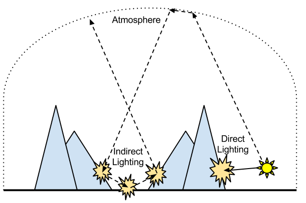
If there is no light, we can see nothing. It sounds very obvious, but we often forget about it. For example, if you go into a room with no window and close the door, you cannot see anything. No matter how long you stay in the dark, you can't see a thing… well, unless there is a seam under the door or something. The reason why we keep forgetting this obvious fact is because it is really hard to find a complete dark place in the real world. Why is it so? It's because light reflects off objects endlessly, and the reflected light eventually reaches our eyes. This type of light is called indirect light. On the other hand, direct light is the light directly coming from a light source. An example is shown in Figure 4.1.
.png)
Figure 4.1 An example of direct and indirect light
Between direct and indirect light, which one would be easier to calculate? As the above picture hint, the answer is direct light. Indirect light goes through multiple reflections, so it is inherently harder to calculate. As one of the methods to calculate indirect light, there is a technique called Ray Tracing. Readers who are interested in 3D graphics probably heard about it, but this technique is still not widely used in computer games due to hardware limitations.[1] Therefore, most real-time 3D applications, including computer games, are still calculating only direct light “properly”, and trying to mimic indirect light. That is why this book only covers direct light.[2] By the way, the lighting techniques covered in this chapter are still widely used in most games, so make sure you understand them very well.
In computer graphics, we like to think light is made of two major components: diffuse and specular light, so we will look at these two separately in this chapter.
Diffuse Light
Background
Although most objects don't emit light by themselves, the reason why we can still recognize them is because light emitted from other objects, such as the sun, reflects off them. When this happens, some light is evenly reflected to all directions. We call this diffuse light. Have you ever wondered why an object's color and darkness do not change regardless where you look at it from? It is because of diffuse light, which is evenly reflected to all directions. If it is reflected to only one direction[3], you should be able to recognize the object only from a certain direction.
By the way, a rougher surface usually reflects more diffuse light.[4]
Maybe a drawing will help.
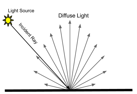
Figure 4.2 Diffuse lighting
One thing that I didn't show you in Figure 4.2 is specular light that we will learn shortly. Don't worry about this for now, and just remember that some part of an incoming light becomes diffuse light, and some other part becomes specular light.
Well, then how do we calculate diffuse lighting? As one can guess, there are various diffuse lighting models created by many great mathematicians. Out of these, we will learn only one simple diffuse lighting model, called Lambert diffuse lighting model, which happens to be a very popular lighting model in computer games. Lambert diffuse lighting model, which was created by a mathematician named Johann Heinrich Lambert, says the amount of diffuse light at a point on a surface is same as the cosine value of the angle between the surface normal[5] and the incoming light ray. Then, let's observe the cosine graph shown in Figure 4.3.
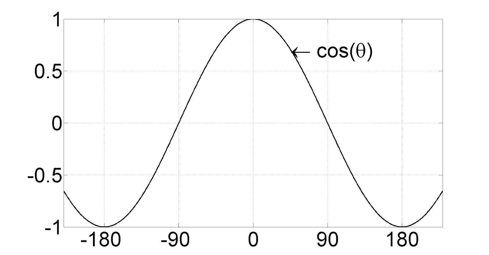
Figure 4.3 A graph showing y = cos(x) function
From the above graph, you can see that the result, or the value on the y-axis, is 1 when the angle is 0. And as the angle grows bigger, the result gets smaller until it becomes 0 at 90 degree. If we go further, the result even becomes negative. With this observation in mind, let's look at Figure 4.4, which shows what happens in the real word depending on the angle of the incoming light rays?
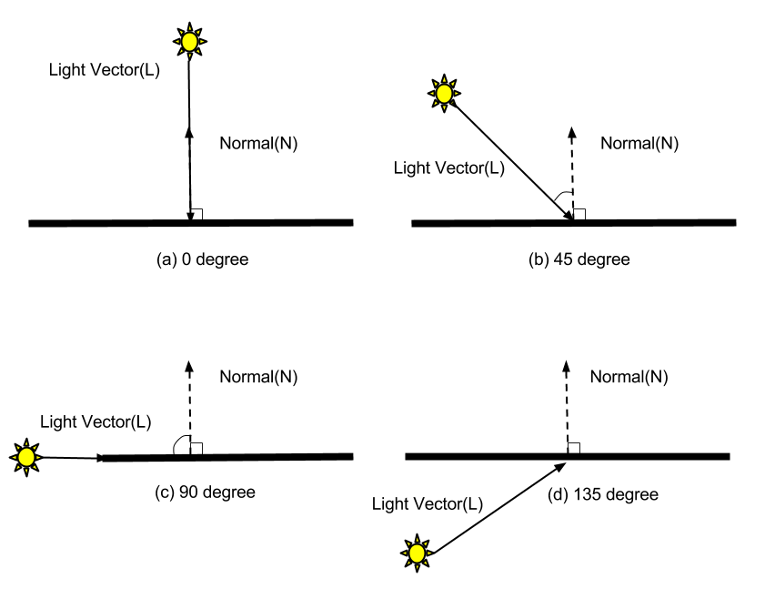
Figure 4.4 Various angles between different light and normal vectors
Can you guess when the surface would be lit brightest? Yes, it is when the sun reaches its highest position in the sky. (Case a) As the sun lowers, the surface gradually gets darker. (Case b) And when the sun finally goes down over the horizon, the surface becomes completely dark. (Case c) Then, what happens after the sunset? The surface will remain dark because it is not getting any light. (Case d) Then let's turn this observation into a graph. The angle between the surface normal and the sun is on the x-axis and the brightness of the surface is on the y-axis. The range of the y-axis is [0, 1]: 0 is when the surface is darkest, and 1 is when the surface is brightest.

Figure 4.5 A graph showing our observation
The reason why I put question marks between -90 ~ 90 degrees in the above figure is because it is still unknown how fast the surface darkens as the angle decreases. Now let's compare this figure to Figure 4.3. If you clamp any negative values to 0 in Figure 4.3, it looks almost identical to our current figure, right? The only difference is that the falloff speed between -90 and 90 is a bit different. Then, can we just believe that uncle Lambert derived this cosine formula after through observations? Yes, at least I'd love to! :P
Then we should be able to calculate diffuse light with a cosine function if we use the Lambert model! However, cosine is not a cheap function, so calling it every time in pixel shader makes me feel icky. Is there any alternative? Yes. If you flip through you math book, you will find a section where it says dot product can replace cosine… well, only under certain conditions.
θ = angle between A and B
| A | = length of vector A
| B | = length of vector B
A ∙ B = cosθ | A || B |
In other words,
cosθ = (A ∙ B) ÷ (| A |ⅹ| B |);
According to the above dot product formula, the cosine value of an angle between two vectors is same as two vector's dot product divided by the multiplication of lengths of two vectors. If we simplify this formula even further by making the lengths of both vectors to 1.
cosθ = (A' ∙ B')
The simplified formula says if you take the cosine of the angle between two vectors, it's same as the dot product of them. But here's a question: is it okay to change the lengths of vectors like this? In other words, the lengths of the normal and light vectors are important while diffuse light is calculated? No, not at all. What matters is only the angel between two vectors, and the lengths don't affect the result, at all. Therefore, it sounds much better to make the lengths to 1 to simplify the formula.[6]
Do you want to know why a dot product is better than cosine? Let (a, b, c) be vector A, and (d, e, f) be vector B. Then you can find the dot product very easily like this:
A ∙ B = (a ⅹ d) + (b ⅹ e) + (c ⅹ f)
This looks much simpler than cosine function, right? If I ask you to calculate the cosine value, I'm pretty sure you will be slower than doing three multiplications followed by two additions. :P
Okay, I think we learned enough to write diffuse lighting shader code.
Initial Step-by-Step Setup
- As we did in other chapters, create a new DirectX effect inside RenderMonkey, and delete all the code inside vertex and pixel shaders.
- Now change the shader name to Lighting.
- Don't forget to add gWorldMatrix, gViewMatrix and gProjectionMatrix, and assign proper semantics for them. They are needed to transform vertex positions.
What information did we need to calculate diffuse lighting with the Lambert model? The light and normal vectors, right? Normal information is normally stored in each vertex,[7] so we should get it from the vertex buffer. Do you remember what extra step we had to perform to get the UV coordinates from vertex buffer in Chapter 3? From Workspace panel, double-click on Stream Mapping and add a new field named NORMAL. Normal is a direction vector that exists in a 3D world, so it will be declared as FLOAT3. Again, you don't need to worry about Attribute Name, but make sure that Index is 0.
Then, how do we find the light vector? This is not that hard. If you just a draw a line from the position of the light source to the current pixel position, that is what we are looking for. So once the light position is known, we can find the light vector very easily. Then how is the light position defined? Something like “the light is at (500, 500, -500) in the world” should be enough. This means that the light position is a global variable. From Workspace panel, right-click on Lighting, and select Add Variable > Float > Float4. Then, change the name of the newly-created variable to gWorldLightPosition. Finally, double-click the variable and set the values to (500, 500, -500, 1).
Once you are done, RenderMonkey Workspace should look like Figure 4.6.
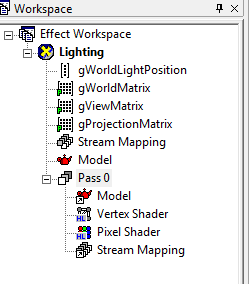
Figure 4.6 RenderMonkey project after the initial setup
Vertex Shader
I will show you the full source code first, and provide line-by-line explanation after.
struct VS_INPUT
{
  float4 mPosition : POSITION;
  float3 mNormal : NORMAL;
};

struct VS_OUTPUT
{
  float4 mPosition : POSITION;
  float3 mDiffuse : TEXCOORD1;
};

float4x4 gWorldMatrix;
float4x4 gViewMatrix;
float4x4 gProjectionMatrix;

float4 gWorldLightPosition;

VS_OUTPUT vs_main( VS_INPUT Input )
{
  VS_OUTPUT Output;

  Output.mPosition = mul( Input.mPosition, gWorldMatrix );

  float3 lightDir = Output.mPosition.xyz - gWorldLightPosition.xyz;
  lightDir = normalize(lightDir);


  Output.mPosition = mul( Output.mPosition, gViewMatrix );
  Output.mPosition = mul( Output.mPosition, gProjectionMatrix );

  float3 worldNormal = mul( Input.mNormal, (float3x3)gWorldMatrix );
  worldNormal = normalize( worldNormal );

  Output.mDiffuse = dot(-lightDir, worldNormal);

  return Output;
}
Input Data to Vertex Shader
We will start from the input data structure used in Chapter 2.
struct VS_INPUT
{
  float4 mPosition : POSITION;
};
Now we need to add normal here. The semantic for normal is NORMAL. As mentioned earlier, normal is a direction vector in 3D space, so the data type will be float3.
struct VS_INPUT
{
  float4 mPosition : POSITION;
  float3 mNormal : NORMAL;
};
Vertex Shader Function
In this chapter, we will take a look at the vertex shader function before its input and output data. I believe this is an easier way to understand the lighting shaders.
First, we transform the vertex position, as usual.
VS_OUTPUT vs_main( VS_INPUT Input )
{
  VS_OUTPUT Output;

  Output.mPosition = mul( Input.mPosition, gWorldMatrix );

  Output.mPosition = mul( Output.mPosition, gViewMatrix );
  Output.mPosition = mul( Output.mPosition, gProjectionMatrix );
The above code does not need explanation anymore. What other things did we need to calculate diffuse light? We need to find the light and normal vectors, but do we find these in the vertex or in pixel shader? Think about it for a second.
…
So, what do you think? There is no one absolute answer: you can do it in either shader. If we do this in vertex shader, we would calculate the dot product of these two vectors on each vertex, and return the result as part of VS_OUTPUT structure. Then, the output values will be passed to pixel shader after interpolated by interpolators, so we can just use interpolated dot product values in pixel shader.
On the other hand, if you do this in pixel shader, you would return the normal information as part of VS_OUTPUT, and pixel shader will read it to calculate the dot product.
Since there is no difference whether the calculation is done in vertex or pixel shader[8], we should select the option which is better for performance. To see which option is better, let's count how many times each shader is executed.[9] When a triangle is drawn, how many times will the vertex shader run? A triangle consists of three vertices, so the vertex shader is executed three times. Then how about the pixel shader? It will be executed as many times as the pixels covered by this triangle on the screen. If the triangle is really tiny on the screen, thus covering only one pixel, the pixel shader will be executed only once. However, usually a triangle covers more than three pixels on the screen. So, if a same calculation can be done in either vertex or pixel shader, it is better to be done in vertex shader over pixel shader. Therefore, we will calculate diffuse lighting in vertex shader, as well.
Tip: If a calculation can be done either in vertex or pixel shader. It is usually a better idea to do so in the vertex shader for performance reasons.
Then, let's construct the light vector, first. As mentioned earlier, you can do this by drawing a line from the light position to current position. “Drawing a line” between two points is same as subtracting a position vector from another. So, if you subtract the light position from current position, you can get the light vector. However, there is one thing that we should be careful about. To get the correct result in 3D math, all variables must be in a same space. We defined the light position in the world space, right? But, which space is the vertex position defined in? Input.mPosition is in the local space, and Output.mPosition is in the projection space, but what we really need is the position in the world space. If you look at the vertex shader code listed above, you will see some empty lines after multiplying the world matrix to the local position. Output.mPosition right after the world matrix multiplication is the position in the world space, so we can just subtract the light position from it. Now replace the empty lines with the light vector construction code shown below:
float3 lightDir = Output.mPosition.xyz - gWorldLightPosition.xyz;
K, now it is time to make the vector's length to 1. I told you the reason for this is to use a dot product instead of a rather expensive cosine function. Did I also tell you an operation of making a vector's length to 1 is called normalization? To manually normalize a vector, you can divide each components of the vector by the length of the vector. However, we will just use a HLSL intrinsic function, normalize(). Yay for another magic function!
lightDir = normalize(lightDir);
Now that we have prepared the light vector, it is time to find the normal vector. Can we just use the normal information from the input data as-is? To find the answer, think about in which space the vector lives. Since this data directly comes from the vertex buffer, it must be in the local space. Now we know we need to transform it to the world space to calculate diffuse lighting properly.
Caution: While performing any 3D operation, we have to make sure that all the variables are in a same space.
float3 worldNormal = mul( Input.mNormal, (float3x3)gWorldMatrix );
Do you see we are casting the world matrix to a 3-by-3 matrix? We prefixed (float3x3) to do so. In a 4-by-4 matrix, the fourth row (or column) contains translation information, so it does not affect direction vectors, at all.[10]
Don't forget to change this vector to a unit vector, as well.
worldNormal = normalize( worldNormal );
Now we have all two vectors we need, so let's find the dot product of them. Do you still remember what the dot product formula was? Although it was not hard, you do not need to remember it at all because we will just use another HLSL intrinsic function, dot() for this.
Output.mDiffuse = dot(-lightDir, worldNormal);
The above code assigns the dot product result to mDiffuse of the return structure. Oh, another thing! Do you see we used -lightDir instead of lightDir here? The reason why we did this is because the tails of two vector must meet to calculate the dot product correctly. So, if lightDir was used, the light vector's header would meet the normal vector's tail, resulting in a wrong calculation.
Also do you see that float3 is used for mDiffuse to store the dot product result, which is only a single float? If you assign a float value to a float3 variable, all three components of the variable will have the same float value. So, the above code is same as assigning dot(-lightDir, worldNormal).xxx.
Now simply returns the result.
  return Output;
}
Global Variables
Have you figured out by now why I wanted explained the vertex shader function first? It is because it made no sense to say “I'm going to declare the light position as a global variable” without any explanation.
Please add these global variables at the top of the source code.
float4x4 gWorldMatrix;
float4x4 gViewMatrix;
float4x4 gProjectionMatrix;

float4 gWorldLightPosition;
Output Data from Vertex Shader
As we saw while writing the vertex shader function, the output data is mPosition and mDiffuse. We already know float4 and POSITION semantic are used for the position. Then, what type and semantic should be used for mDiffuse? The dot product of two vectors is not a vector: it is just a single real number.[11] Therefore, using float is completely fine, but float3 is used here since we are going to return this value as the RGB values of pixels. Then how about the semantic? Do you think there is a semantic like DIFFUSELIGHTING? Unfortunately, no.[12] While programming shaders, there are often cases where you cannot find a semantic which is specifically made for your specific use. In these cases, TEXCOORD semantic is normally used. There are at least 8 TEXCOORDs[13], so they rarely run out! For this chapter, we will use TEXCOORD1.[14]
Please add the following output structure to the source code.
struct VS_OUTPUT
{
  float4 mPosition : POSITION;
  float3 mDiffuse : TEXCOORD1;
};
Pixel Shader
Alright, pixel shader time! But what do we need to do? We already calculated diffuse lighting in vertex shader. So the only work left for the pixel shader is returning the interpolated diffuse result, which is passed to the pixel shader. If you recall, the dot product is used instead of cosine, so the range of the result is [-1, 1]. But, the range of diffuse lighting is [0, 1], so let's just clamp any negative value to 0. Although we can use an if statement for this, we will instead use a faster HLSL function, saturate(). This function clamps a value to [0, 1]. And even better, it is almost free performance-wise!
struct PS_INPUT
{
  float3 mDiffuse : TEXCOORD1;
};

float4 ps_main(PS_INPUT Input) : COLOR
{
  float3 diffuse = saturate(Input.mDiffuse);
  return float4(diffuse, 1);
}
In the above code, the return value is constructed with float4(diffuse, 1). Just remember that this is a way to construct a float4 variable.
Now press F5 to compile vertex and pixel shaders separately before seeing the preview window. You will see a sphere which is lit with very smooth diffuse light, as shown in Figure 4.7.
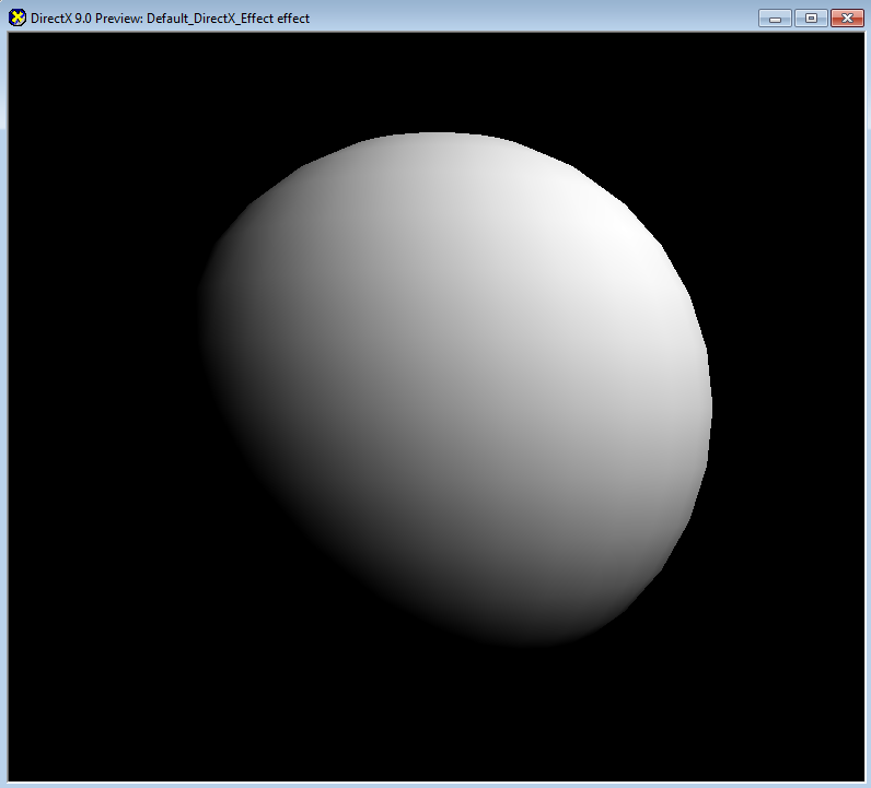
Figure 4.7 Our diffuse lighting effect!
Footnotes:
- Especially video game console hardware is a problem.
- Lighting models that only consider direct light are called local illumination models, while ones that also consider indirect light are called global illumination models.
- This is specular lighting, which we will cover later in this chapter.
- There are not many objects which doesn't reflect diffuse light at all. Even very smooth surfaces reflect diffuse light because light can penetrate through and scatter below the surface until it finally comes out of the surface.
- Normal is a direction vector that represents a surface's orientation. Therefore, the normal vector of a horizontally flat surface is perpendicular to the surface facing upward.
- A vector whose length is 1 is called a unit vector. And a process of making a vector to have a length of 1 is normalization.
- This is not always true. We will see another way of finding normal while implementing Normal Mapping shader later in this book.
- In fact, there is a subtle difference between these two approaches.
- There are also other factors that might degrade the performance, so this is a guideline only.
- Think it this way. The direction which an arrow is pointing to doesn't change, even if it is moved around without any. So translation value has no meaning to a direction vector.
- This is called scalar.
- Some people use COLOR0 semantic for this, but this book does not. In vertex shader 2.0 spec, a value with COLOR semantic is clamped to [0, 1], and the interpolated values passed to pixel shader seem to have small errors because of this.
- TEXCOORD0 ~ TEXCOORD7
- The reason why TEXCOORD1 is used instead of TEXCOORD1 is because we will use TEXCOORD0 for the UV coordinates of a texture in the next chapter.