04. Basic Lighting Shader - Part 2

Specular Light
Background
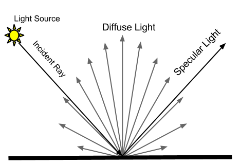
Specular light is different from diffuse light in a way that it only reflects to one direction and the angle of incidence is same as the angle of reflection. So if you want to observe specular light in action, you will have to see the surface from the direction where the reflected rays point toward. Have you ever turned your head away because the sun glare is too bright on your monitor? If you tilt the monitor a bit, it is bearable, right? That is specular light.
Then let's add specular light to Figure 4.2, which had only diffuse light.
.png)
Figure 4.8 Diffuse and specular light
Just like diffuse light, there are many different specular lighting models, too. In this book, we will use Phong model, which is widely used in video games. In order to calculate specular lighting, Phong model finds the cosine value of the angle between the reflect vector (light vector reflected off the surface) and camera vector (a vector from the camera position to the current position), and raises the result to the power of some exponent. Look at the picture below for better understanding.
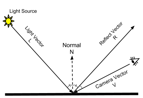
Figure 4.9 An example of specular lighting
Finding the cosine of the angle between reflect vector, R, and camera vector, V, is not different from what we did for diffuse lighting except that R and V are used instead of normal and light vectors. By the way, why do we raise cosine to the power of an exponent? You will find the answer in Figure 4.10.
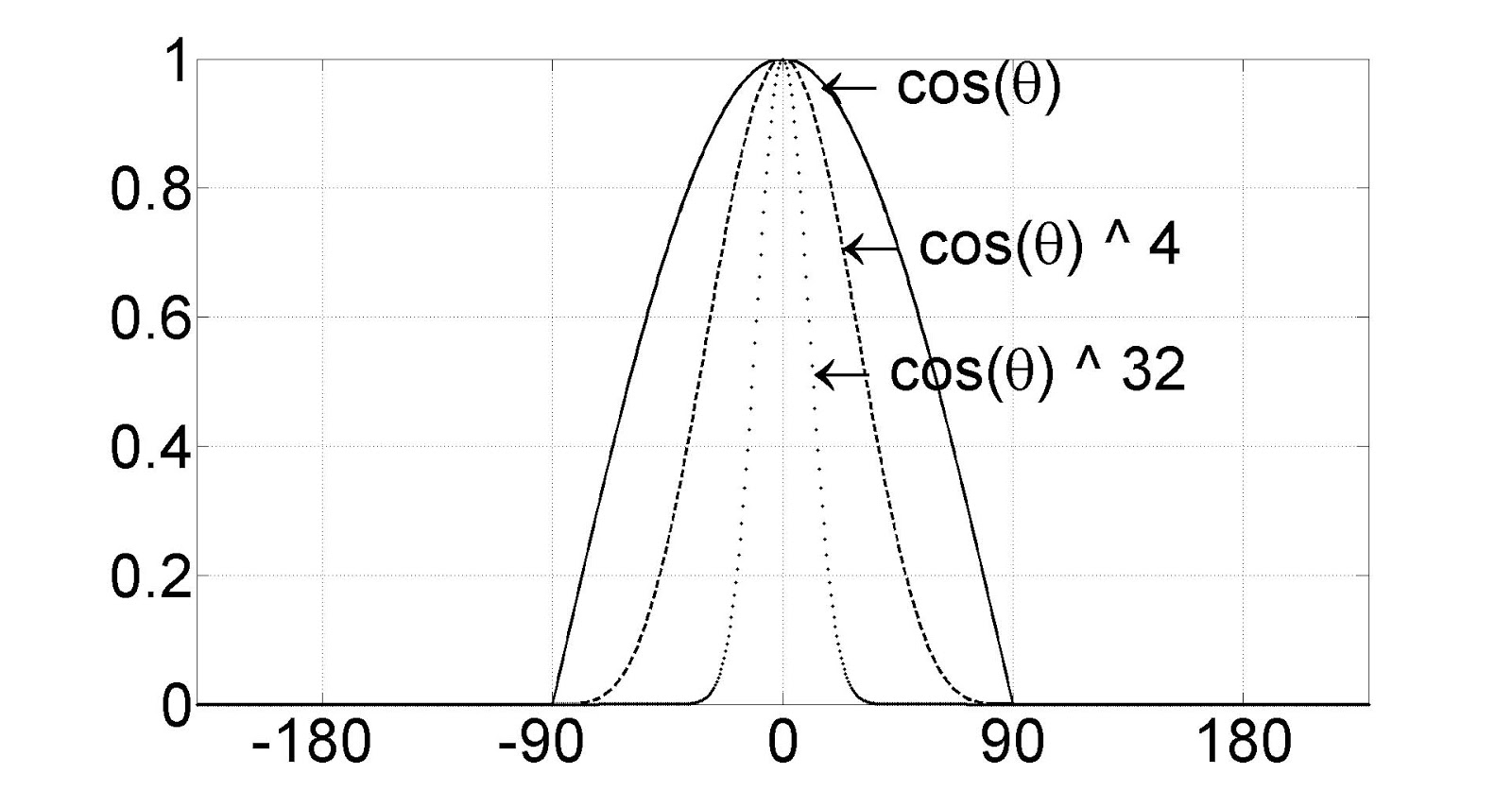
Figure 4.10 As the exponent gets bigger, the cosine graph falls faster.
You see the graph falls faster as the exponent grows, right? If you observe specular light in the real world, you will notice that radius of the light is very tight unlike diffuse light, which is rather wide. This is why we use the power function: to mimic the tightness.[1] Then, what exponent should we use? It depends on the materials of surfaces. Rougher surfaces have less tight specular light, so the smaller exponent should be used. As a general rule, start from an exponent of 20, and experiment with bigger and smaller numbers.
Now let's write some shader code.
Initial Step-by-Step Setup
Let's add specular light to the diffuse light shader we wrote earlier in this chapter. After all, we need both diffuse and specular to get a “correct” light effect.
What were the new things added to Figure 4.9? They were reflect and camera vectors, right? Reflect vector is a light vector which is reflected off the surface, and the angel between normal and light vectors is same as the angle between normal and reflect vectors. This means that reflect vector can be found from all the information we already have. Then, what about camera vector? Just like how we found the light vector, we can draw a line from the camera position to the current position, right? Therefore, the camera position will be a global variable. Go to RenderMonkey, and right-click on Lighting effect to add a new float4 variable. gWorldCameraPosition should be good for the name. Now right-click on it and assign ViewPosition semantic.
Now we got everything we need. Let's look at the vertex shader.
Vertex Shader
Just like before, the full source code is listed first.
float4x4 gWorldMatrix;
float4x4 gViewMatrix;
float4x4 gProjectionMatrix;

float4 gWorldLightPosition;
float4 gWorldCameraPosition;

struct VS_INPUT
{
    float4 mPosition : POSITION;
    float3 mNormal: NORMAL;
};

struct VS_OUTPUT
{
    float4 mPosition : POSITION;
    float3 mDiffuse : TEXCOORD1;
    float3 mViewDir: TEXCOORD2;
    float3 mReflection: TEXCOORD3;
};

VS_OUTPUT vs_main( VS_INPUT Input )
{
    VS_OUTPUT Output;

    Output.mPosition = mul( Input.mPosition, gWorldMatrix );

    float3 lightDir = Output.mPosition.xyz - gWorldLightPosition.xyz;
    float3 lightDirUnnorm = lightDir;
    lightDir = normalize(lightDir);

    Output.mViewDir = Output.mPosition.xyz - gWorldCameraPosition.xyz;

    Output.mPosition = mul( Output.mPosition, gViewMatrix );
    Output.mPosition = mul( Output.mPosition, gProjectionMatrix );

    float3 worldNormal = mul( Input.mNormal, (float3x3)gWorldMatrix );
    worldNormal = normalize(worldNormal);

    Output.mDiffuse = dot(-lightDir, worldNormal);
    Output.mReflection = reflect(lightDirUnnorm, worldNormal);

    return Output;
}
Global Variables and Input Data of Vertex Shader
Let's take a look at the input data to vertex shader. Do we need any extra vertex information? I can't think of any, so there must be none. :P Let's just use the same input structure we used earlier in this chapter.
Then how about global variables? We have to declare gWorldCameraPosition that we just added to the RenderMonkey project, right? Add the following line:
float4 gWorldCameraPosition;
Output Data from Vertex Shader
Let's look at the vertex shader's output data. As we did with diffuse light, can we calculate the specular light in vertex shader and pass the result to pixel shader? Unfortunately, no. To calculate the specular light, we have to raise the cosine value to the power of an exponent, but doing it so before the interpolation step produces a wrong result. This is because the power function is not linear. This means that we need to calculate specular light in pixel shader, so we will find two directional vectors, R and V in vertex shader and pass them to pixel shader. Please add the following lines to VS_OUTPUT structure.
    float3 mViewDir: TEXCOORD2;
    float3 mReflection: TEXCOORD3;
Vertex Shader Function
K, now let's find these two vectors. Remember how we can find the camera vector? It's simple. Just draw a line from the camera position to current position. This is not different from finding a light vector, at all. Let's add the camera vector code right below where we calculated the light vector.
Output.mViewDir = Output.mPosition.xyz - gWorldCameraPosition.xyz;
Now it's time to find the reflect vector. Then what is the math formula for vector reflection? Guess what? I don't even remember! But don't worry. There is another magic HLSL function for this. It's called reflect(). This function takes two parameters, light and surface normal vectors. Add the following line before the Output structure is returned
Output.mReflection = reflect(lightDirUnnorm, worldNormal);
In the above code, we used a variable that's not defined yet: lightDirUnnorm. This is the unnormalized light vector, which we don't have yet. It is best not to normalize vectors which will be passed to pixel shaders to avoid visual artifacts on large triangles. That's why we did not normalize mViewDir either. But you might still see some artifacts because we calculated the reflection vector in vertex shader. In rare cases, the reflection vector might become 0 during interpolation. If you see this symptom, find the reflection vector in pixel shader. Anyways, add the following line right below where lightDir was defined to remember the unnormalized light vector:
float3 lightDirUnnorm = lightDir;
Now that we found both vectors we need, there's nothing more to do in vertex shader.
Pixel Shader
Let's see the full pixel shader code first.
struct PS_INPUT
{
    float3 mDiffuse : TEXCOORD1;
    float3 mViewDir: TEXCOORD2;
    float3 mReflection: TEXCOORD3;
};

float4 ps_main(PS_INPUT Input) : COLOR
{
    float3 diffuse = saturate(Input.mDiffuse);

    float3 reflection = normalize(Input.mReflection);
    float3 viewDir = normalize(Input.mViewDir);
    float3 specular = 0;
    if ( diffuse.x > 0 )
    {
        specular = saturate(dot(reflection, -viewDir ));
        specular = pow(specular, 20.0f);
    }

    float3 ambient = float3(0.1f, 0.1f, 0.1f);

    return float4(ambient + diffuse + specular, 1);
}
First add the following two vectors to PS_INPUT structure. These are exactly same as what we added to VS_OUTPUT structure.
    float3 mViewDir: TEXCOORD2;
    float3 mReflection: TEXCOORD3;
We will add some new code right after where we calculated diffuse lighting earlier in this chapter. First, normalize mReflection and mViewDir.
    float3 reflection = normalize(Input.mReflection);
    float3 viewDir = normalize(Input.mViewDir);
Then, find the dot product of these two vectors and raise it to the 20th power.
    float3 specular = 0;
    if ( diffuse.x > 0 )
    {
        specular = saturate(dot(reflection, -viewDir ));
        specular = pow(specular, 20.0f);
    }
From the above code, we calculate specular light only when diffuse light is bigger than 0%. It's because there's no light hitting the surface if there is no diffuse light, so specular light cannot exist there, either. Also you must have noticed that –viewDir is used when calculating the dot product, right? As with diffuse light, two vectors' tails must meet to calculate specular light correctly.
Also please note that pow() is used to raise the value to the 20th power. The exponent 20 would be different for different objects.[2] So declaring it as a global float variable would be a good idea if you need different specular tightness for different objects. I will leave this task to readers. Now it's time to return the result. Let's return only specular light first. Replace the return statement with the following line.
return float4(specular, 1);
Once you compile and run the shader, you will see specular light, as shown in Figure 4.11.
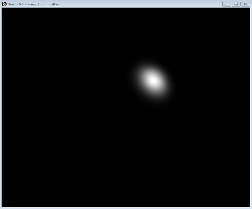
** Figure 4.11 Specular light has much stronger and tighter highlight than diffuse light**
Now you know how specular light looks like. If we add diffuse light to this, the result will be more perfect. Please change the return code like this:
return float4(diffuse + specular, 1);
There are cases when the addition of diffuse and specular becomes bigger than 1. Luckily, you don't need to worry about this because the result is automatically clamped to 1.[3]
If you compile both vertex and pixel shader and see the preview window, you will find a nice looking sphere with both diffuse and specular light.
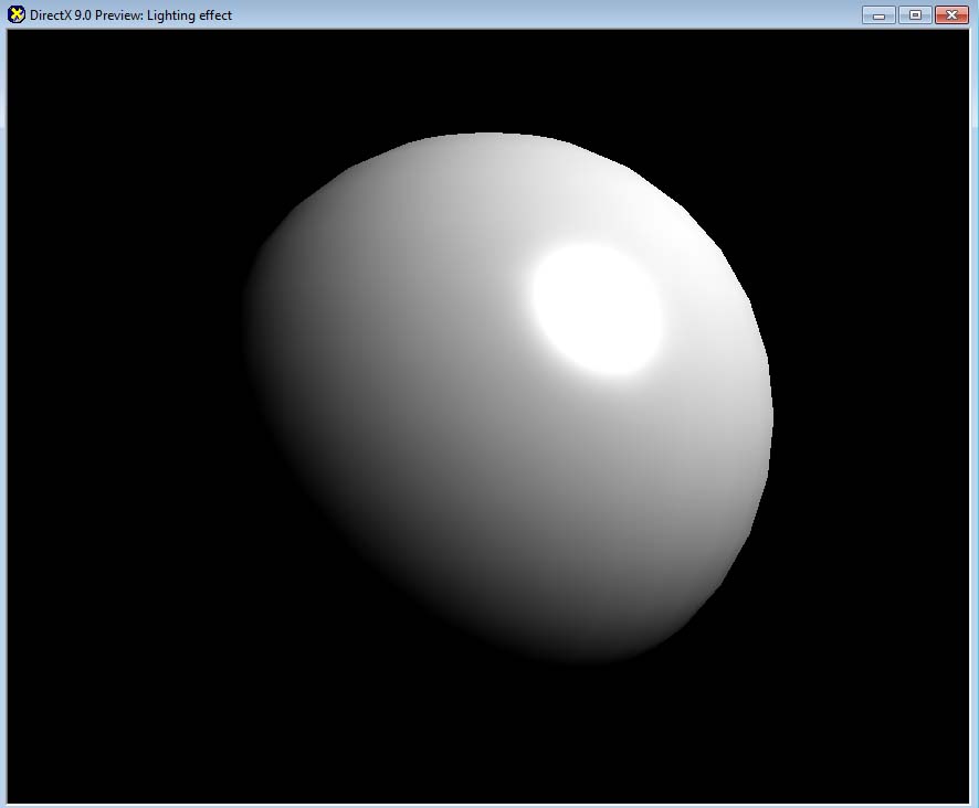
Figure 4.12 Diffuse + Specular
This is already pretty good, but the bottom-left part of the sphere is too dark. In fact, it is almost invisible. As mentioned before, indirect light usually illuminates the dark area in the real world. Then, why don't we just add simple ambient light to brighten the dark area? Let's declare the ambient light as 10% .
float3 ambient = float3(0.1f, 0.1f, 0.1f);
Then, add this ambient amount to the final return value.
return float4(ambient + diffuse + specular, 1);
After this, you will see the result like Figure 4.13.
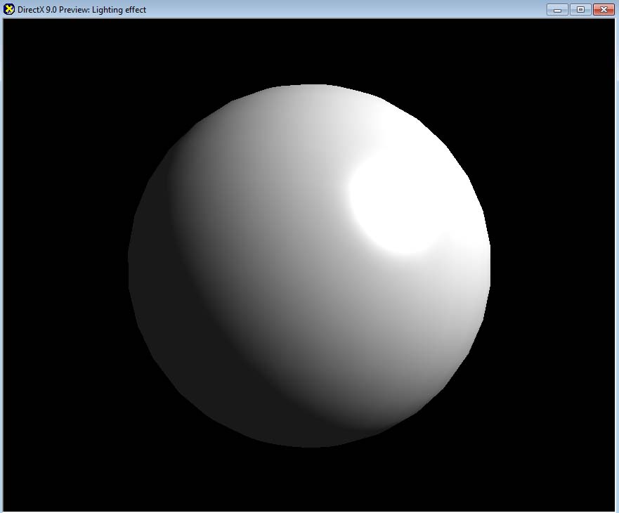
Figure 4.13 Ambient + Diffuse + Specular
(Optional) DirectX Framework
This is an optional section for readers who want to use shaders in a C++ DirectX framework.
First, make a copy of the framework used in Chapter 3 and save it into a new folder. Next, save the shader and 3D model that we used in RenderMonkey into Sphere.x and Lighting.fx files so that they can be used in the DirectX framework.
Then, open the solution file in Visual C++. We will look at the global variables first. Since we don't use any texture in this chapter, delete the texture variable declared in the last chapter. Its name was gpEarthDM. Now change the name of the shader variable from gpTextureMappingShader to gpLightingShader. Now it is time to declare new variables for the light and camera positions. Both of them are in the world space. First, we will reuse the same light position used in RenderMonkey.
// world position of the light
D3DXVECTOR4 gWorldLightPosition(500.0f, 500.0f, -500.0f, 1.0f);
For the camera position, we are using the same values defined in RenderScene() function in the last chapter.
// world position of the camera
D3DXVECTOR4 gWorldCameraPosition(0.0f, 0.0f, -200.0f, 1.0f);
Now go to CleanUp() function. Since gpEarthDM texture is not used anymore, delete the code which was releasing the texture.
Next up is LoadAssets() function. Again, delete the code which was loading gpEarthDM texture. And change the shader's name to Lighting.fx. Don't forget to change the variable name from gpTextureMappingShader to gpLightingShader.
    // loading textures

    // loading shaders
    gpLightingShader = LoadShader("Lighting.fx");
    if (!gpLightingShader)
    {
        return false;
    }
Lastly, we will look at RenderScene() function. First, find all the instance of gpTextureMappingShader, and replace them with gpLightingShader. Now let's look at the code which constructs the view matrix. There was a variable named vEyePt that we used to make the view matrix, right? This variable's value is same as gWorldCameraPosition, so we will reuse this value.
Change below code
D3DXVECTOR3 vEyePt( 0.0f, 0.0f, -200.0f );
to this:
    D3DXVECTOR3 vEyePt( gWorldCameraPosition.x, gWorldCameraPosition.y,
        gWorldCameraPosition.z );
Now delete gpLightingShader->SetTexture() code. The shader in this chapter does not use a texture, so we don't need this code. Then, pass the light and camera positions to the shader. Since the data type is D3DXVECTOR4, we will call SetVector() function.
    gpLightingShader->SetVector("gWorldLightPosition", &gWorldLightPosition);
    gpLightingShader->SetVector("gWorldCameraPosition", &gWorldCameraPosition);
Now compile and run the shader. You can see the same visual that you saw in RenderMonkey, right?
Other Lighting Techniques
Still the most common lighting techniques in computer games is Lambert + Phong, but now there are more games using more advanced lighting techniques. For the readers who want to learn more about advanced lighting techniques, I will mention some of them in the following list:
- Blinn-Phong: a technique that is very similar to Phong.
- Oren-Nayar: a diffuse lighting technique that takes account of the roughness of a surface.
- Cook-Torrance: a specular lighting technique that takes account of surface roughness
- Spherical Harmonics Lighting: once indirect light is preprocessed offline, it can be applied in real-time.
Summary
A quick summary of what we learned in this chapter:
- Both Lambert and Phong models use cosine function.
- Phong specular lighting model uses pow() function.
- Once you change the vector's length to 1, a dot product can replace cosine.
- If a same calculation can be done either in vertex and pixel shader, doing it in vertex shader is a better choice.
- There are more realistic, but more complicated techniques. Some of them are already used in recent computer games.
With the completion of lighting shader, now we have learned all the basic shaders. We will mix and match what we have learned so far to implement more practical techniques. So if there was anything you are unsure about from Chapter 1 to 4, please review it before coming to Chapter 5.
Footnotes:
- This was invented as a hack, which has no physical correctness, but still is used a lot in games.
- Higher exponents produce tighter specular light. Experiment with different numbers.
- It is because our back buffer format is 8 bit per channel. If a floating-point texture is used, values bigger than 1 can be stored, as well.