03. Texture Mapping


New HLSL in this chapter
- sampler2D: a texture sampler data type which is used to get a texel from a texture
- tex2D(): a HLSL function to sample a texel from a texture
- swizzling: a way to access the components of a vector in an arbitrary order
What did you think about what we covered in the last chapter? Too easy? It didn't seem that useful for the game you are trying to make? Yeah, you are right. The main goal of the last chapter was learning the basic syntax of HLSL through a simple practice. Just consider it as a hello-world program in other programming languages. Now, you are going to learn something more useful in this chapter. What about wrapping the red sphere with an image? You know this is called Texture Mapping, right?
Texture Mapping and UV Coordinates
As mentioned earlier in this book, the building blocks of a 3D object are triangles. Then, what's involved to put an image, or a texture, on a triangle? We should order the GPU like this: "Show the pixel at the right-bottom corner of that image on the left vertex of this triangle"[1] We all know that a triangle is made of three vertices, so all we need to do is mapping each of three vertices to a pixel in a texture. Then how do we specify one pixel on a texture? A texture is an image file after all, so can we just say something like "the pixel at x = 30, y = 101"? But, what happens if we doubles the width and height of the image? We will have to change it to "x = 60, y = 202". This is not good, at all!
Let's take a moment and think about a common sense that we learned in the last chapter. We did something very similar with the color representation. To represent a color in a uniform way regardless the number of bits per channel, we used the percentage notation [0~1]. So why don't we just use the same method? Let's say x = 0 points to the very left column of a texture, and x = 1 points to the very right column. Similarly, y = 0 is the top row and y = 1 is the bottom row. By the way, the UV notation is normally used instead of XY for texture mapping; there is no special reason, it's just to avoid any confusion since XY is normally associated with positions. Figure 3.1 shows what we just discussed here:
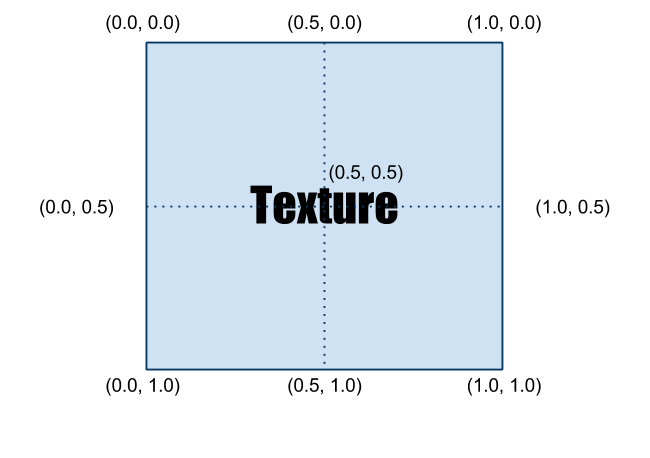.png)
Figure 3.1 UV layout on a texture
Now let's see some examples of how different UV coordinates change the visuals. Please look at Figure 3.2.
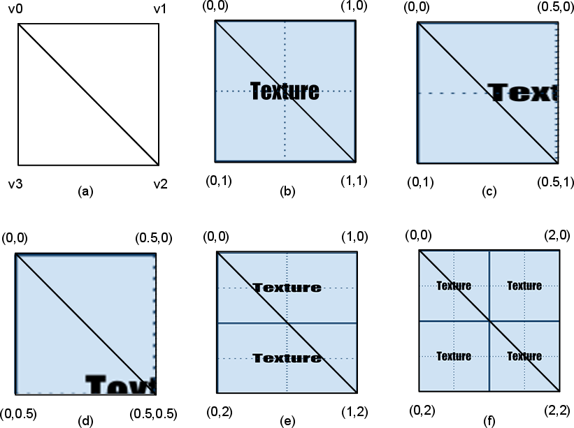
Figure 3.2 Various examples of texture mapping
(a) 2 triangles with no texture. Vertices v0, v1, v2 and v0, v2, v3 are making up one triangle each.
(b) The range of UV coordinates is [0, 0] ~ [1, 1]. It shows a full texture.
(c) The range of UV coordinates is [0, 0] ~ [0.5, 1]. It shows only the left half of the texture. 0.5 means 50%, so it's halfway, right?
(d) The range of UV coordinates is [0, 0] ~ [0.5, 0.5]. So it only shows the top left quarter of the image.
(e) The range of UV coordinates is [0, 0] ~ [1, 2]. It repeats the texture twice vertically. [2]
(f) The range of UV coordinates is [0, 0] ~ [2, 2]. It repeats the texture twice vertically and twice horizontally. [3]
Additionally, you can flip the texture horizontally if the range of UV coordinates is set to [1, 0] ~ [0, 1]. I believe it's enough for you to understand how UV coordinates work. Then, it is about time to write Texture Mapping shader, finally!
Initial Step-by-Step Setup
- As we did in Chapter 2, open RenderMonkey to make a new DirectX effect. Then, delete all the code inside the vertex and pixel shaders.
- Now, change the name of shader to TextureMapping.
- Don't forget to add gWorldMatrix, gViewMatrix and gProjectionMatrix variables that are needed to transform vertex positions. You still remember how to use variable semantics to pass the data, right?
- Next, we will add an image that is going to be used as the texture. Right-click on TextureMapping shader and select Add Texture > Add 2D Texture > [RenderMonkey installation folder]\examples\media\textures\earth.jpg. Now you will see a texture, named Earth, is added.
- Change the name of texture to DiffuseMap.
- Now, right-click on Pass 0 and select Add Texture Object > DiffuseMap. You should be able to see a newly added texture object, named Texture0.
- Change the name from Texture0 to DiffuseSampler.
Once you finish these steps, the Workspace panel should look like Figure 3.3.
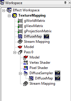
Figure 3.3 RenderMonkey project after the initial setup
Vertex Shader
The full source code is listed below, followed by line-by-line explanation.
struct VS_INPUT
{
 float4 mPosition : POSITION;
 float2 mTexCoord : TEXCOORD0;
};

struct VS_OUTPUT
{
 float4 mPosition : POSITION;
 float2 mTexCoord : TEXCOORD0;
};

float4x4 gWorldMatrix;
float4x4 gViewMatrix;
float4x4 gProjectionMatrix;

VS_OUTPUT vs_main(VS_INPUT Input)
{
 VS_OUTPUT Output;

 Output.mPosition = mul(Input.mPosition, gWorldMatrix);
 Output.mPosition = mul(Output.mPosition, gViewMatrix);
 Output.mPosition = mul(Output.mPosition, gProjectionMatrix);

 Output.mTexCoord = Input.mTexCoord;

 return Output;
}
Before walking through the vertex shader code, let's take a moment and think about what kind of new data is needed to perform texture mapping. Obviously, we need an image, which is going to be used as the texture. Then where should we perform the actual texture mapping between the vertex and pixel shaders? If you think about where vertex and pixel shaders are executed, you can find the answer easily. A vertex shader is executed for each vertices, but where the texture will be shown? Is it on vertices? No, it's not. We want to see the texture on all the pixels inside of a triangle, so texture mapping got to be performed inside the pixel shader, which is executed for each pixels. Then, now we know that it's unnecessary to declare a texture variable inside of vertex shaders.
Then, is there any other information required for texture mapping? It was mentioned earlier in this chapter. Yes, you need the UV coordinates. Do you remember where the UV coordinates are stored? They are stored in vertex data since they can differ across vertices. Therefore, the UV coordinates are passed via vertex data instead of global variables. Now, with this knowledge, let's take a look at the input and output data of the vertex shader.
Input Data to Vertex Shader
We start from the input data structure used in Chapter 2.
struct VS_INPUT
{
  float4 mPosition : POSITION;
};
We will add the UV coordinates to this structure. The UV coordinates have two components, U and V, so the data type should be float2. Then which semantic must be used to retrieve the UV information from the vertex buffer? Just like how the position information was retrieved via POSITION semantic, UV coordinates have their own semantic: TEXCOORD.[4] After adding the data field for UV to the structure, it looks like below:
struct VS_INPUT
{
  float4 mPosition : POSITION;
  float2 mTexCoord : TEXCOORD0;
};
The reason why the number 0 follows TEXCOORD is because multiple TEXCOORDs are supported by HLSL. There are cases where multiple textures are used in a shader. In those cases, you would use different semantics, such as TEXCOORD0, TEXCOORD1 and so on.
Output Data from Vertex Shader
Again, we start from the output structure used in Chapter 2.
struct VS_OUTPUT
{
  float4 mPosition : POSITION;
};
Can you guess if we need to add another information here? One of those things that were not explained in Chapter 2 is that a vertex shader can return more than just the vertex position. The reason why a vertex shader must return a vertex position was to allow the rasterizer to find pixels. However, this is not the reason why a vertex shader returns information other than the position. It does so solely for the pixel shader, and a good example is the UV coordinates.
Pixel shaders cannot directly access the vertex buffer data. Therefore, any data that needs to be accessed by pixel shaders (e.g., UV coordinates) must be passed through vertex shaders. Does it feel like an unnecessary restriction? Once you look at Figure 3.4, you will understand why this restriction exists.
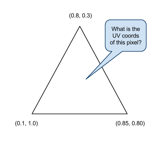
Figure 3.4 What would be the UV coordinates of this pixel?
Where the UV coordinates are defined is on each vertices, but as you can see in Figure 3.4, most pixels' UV coordinates are different from any vertices UV coordinates. [5] Therefore, the right way of finding the correct UV coordinates of a pixel is smoothly blending the UV coordinates defined on three vertices based on the distance from the pixel to each vertices. Luckily, you do not have to do this calculation manually. Just like vertex positions, any other data is automatically handled by a device called interpolator. Let's add the interpolator to the figure of a GPU pipeline presented in Chapter 1.
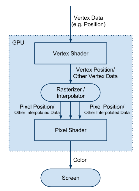
Figure 3.5 Still pretty simple 3D pipeline after adding the interpolator
By the way, this device doesn't stop at interpolating[6] the UV coordinates. It interpolates any data that is returned from vertex shaders and pass the result to pixel shaders.
By now, you should know that the UV coordinates need to be returned from this vertex shader. Let's add the data field.
struct VS_OUTPUT
{
  float4 mPosition : POSITION;
  float2 mTexCoord : TEXCOORD0;
};
Global Variables
We don't need any extra global variables other than what we already used in Chapter 2. So, I'll just show the code again and skip the explanation.
float4x4 gWorldMatrix;
float4x4 gViewMatrix;
float4x4 gProjectionMatrix;
Vertex Shader Function
You heard it enough. The most important responsibility of a vertex shader is transforming vertex positions into the projection space. The below code is identical to the one used in Chapter 2.
VS_OUTPUT vs_main( VS_INPUT Input )
{
 VS_OUTPUT Output;

 Output.mPosition = mul( Input.mPosition, gWorldMatrix );
 Output.mPosition = mul( Output.mPosition, gViewMatrix );
 Output.mPosition = mul( Output.mPosition, gProjectionMatrix );
Now, it's time to pass through the UV coordinates, but do we need to apply any transformation before assigning the UV coordinates to Output structure? The answer is no. UV coordinates do not exist in any 3D spaces discussed in this book. Therefore, we will simply pass the UV coordinates without any transformation.
Output.mTexCoord = Input.mTexCoord;
I cannot think of any other data that needs to be handled here, so I'll finish this function by returning Output.
 return Output;
}
Pixel Shader
As done in Vertex Shader section, the full source code is listed first below:
sampler2D DiffuseSampler;

struct PS_INPUT
{
 float2 mTexCoord : TEXCOORD0;
};

float4 ps_main( PS_INPUT Input ) : COLOR
{
 float4 albedo = tex2D(DiffuseSampler, Input.mTexCoord);
 return albedo.rgba;
}
Input Data to Pixel Shader and Global Variables
It is time to look at the pixel shader. What we need to do here is retrieving a texel [7] from a texture image and output its color on the screen. Then, we need a texture and current pixels' UV coordinates, right? A texture image is uniform for all the pixels, so it would be a global variable. Unlikely, the UV coordinates are part of the input data sent from the vertex shader and passed through the interpolator. First, let's declare the input structure of the pixel shader.
struct PS_INPUT
{
 float2 mTexCoord : TEXCOORD0;
};
Wait. We saw something like this before. It is almost identical to the VS_OUTPUT structure except it is missing mPosition. In fact, the input structure of a pixel shader should match the output structure of its counter-part vertex shader. After all, the pixel shader is getting what is returned from the vertex shader, right?
The next step is texture declaration. Do you remember that we made a texture object named DiffuseSampler while setting up the RenderMonkey project earlier in this chapter? This object is the texture sampler and will be used to retrieve a texel. Therefore, the name of the texture sampler in HLSL must be DiffuseSampler, as well.
sampler2D DiffuseSampler;
sampler2D is another data type that is supported in HLSL, and is used to sample a texel from a 2D texture. There are also other samplers, such as sampler1D, sampler3D and samplerCUBE.
Now, we are ready to write the pixel shader function.
Pixel Shader Function
Let's take a look at the function header first
float4 ps_main( PS_INPUT Input ) : COLOR {
The only difference from previous pixel shader function headers is that it takes a parameter, and its type is PS_INPUT. This is to receive the UV coordinates the interpolator calculated for us. Equipped with the texture sampler and UV coordinates, we can get the value of the texel. A HLSL built-in function, tex2D() can do the magic. tex2D takes two parameters: a texture sampler and UV coordinates, in order.
float4 albedo = tex2D(DiffuseSampler, Input.mTexCoord);
The above code reads a texel which is located at the coordinates which Input.mTexCoord specifies from DiffuseSampler. And the value will be stored in a variable named albedo. Now what do we do with this value? Well, we wanted to show the texture as is, so let's just return it.
return albedo.rgba; }
If we press F5 to compile the vertex and pixel shaders and see the preview window…… uh… it's messed up!
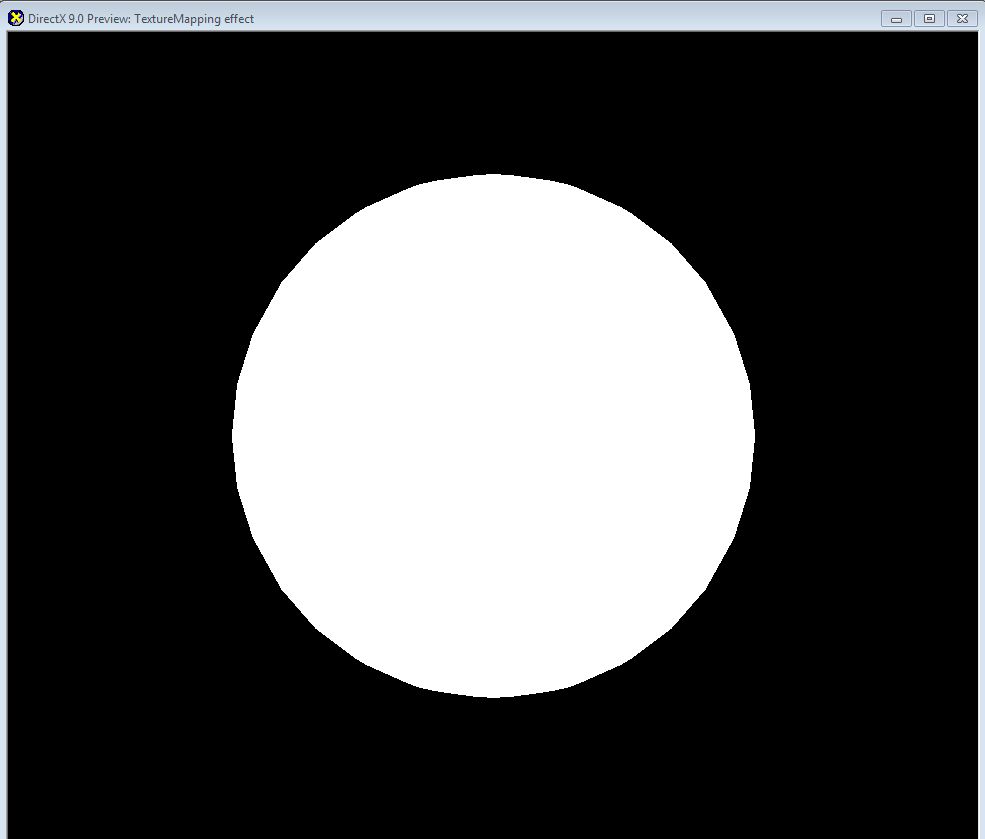
Figure 3.6 Something is messed up here!
Why? It is because that we forgot to map the UV coordinates element in the vertex buffer to the TEXCOORD semantic. To map it properly, go to Workspace panel and left-click on Stream Mapping. There is currently only one entry: POSITION. Now click on Add button to add a new entry, and then change Usage to TEXCOORD. Make sure Index is 0 and Data Type is FLOAT2. You do not need to change Attribute Name. Once you click on OK button, you will see a proper globe as shown in Figure 3.7.
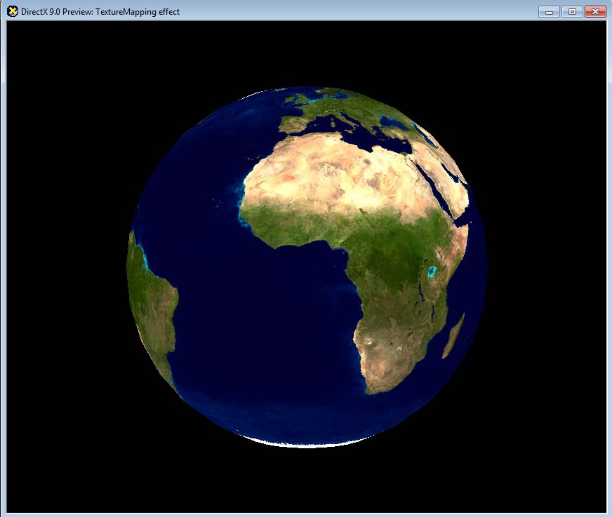
Figure 3.7 A nice looking globe
By the way, did you notice that I used return albedo.rgba; instead of return albedo; while returning the final color? Although it is completely valid to use return albedo;, I intentionally did so to show you something new.
In HLSL, you can attach a postfix, such as .xyzw or .rgba to a vector variable to access the vector's components with ease. For example, if we are dealing with a float4 variable, which has a four components, you can think it as an array of four floats. So if you add .x (or .r), it accesses the first component. Likewise, .y (or .g), .z (or .b) and .w (or .a) point to the second, third and fourth components, respectively. So, if you want to get only the rgb value from albedo, you would do something like this:
float3 rgb = albedo.rgb;
Neat, right? But it does not stop here. You can even change the order of the postfix to access vector components in an arbitrary order. Below example shows how to create a new vector with the same components, but in reverse order.
float4 newAlbedo = albedo.bgra;
Or you can even repeat only one channel three times like this:
float4 newAlbedo = albedo.rrra;
Pretty rad. We refer this technique, which allows us to access vectors' components in any arbitrary order, swizzling.
Maybe you can do some practice here. How about switching the red and blue channels of the globe? Go ahead and try it. It should be a piece of cake for you. :-)
(Optional): DirectX Framework
This is an optional section for readers who want to use shaders in a C++ DirectX framework.
First, make a copy of the framework that we used in Chapter 2 into a new directory. Then, save the shader and 3D model into TextureMapping.fx and Sphere.x respectively so that they can be used in the DirectX framework. Also make a copy of earth.jpg texture file that we used in RenderMonkey. You can find this file in \Examples\Media\Textures folder from RenderMonkey installation folder.
First, let's look at the global variables. In Chapter 2, we used gpColorShader variable for the shader. Change the name to gpTextureMappingShader:
// Shaders
LPD3DXEFFECTgpTextureMappingShader = NULL;
Also, we need to declare a texture pointer, which will be used to store the globe texture.
// Textures
LPDIRECT3DTEXTURE9 gpEarthDM = NULL;
Don't forget to release D3D resources that we just declared. Go to CleanUp() function to do so. Doing so makes you a good programmer. You know that, right? ;) Also don't forget to change the name of gpColourShader.
 // release shaders
 if (gpTextureMappingShader)
 {
  gpTextureMappingShader->Release();
  gpTextureMappingShader = NULL;
 }

 // release textures
 if (gpEarthDM)
 {
  gpEarthDM->Release();
  gpEarthDM = NULL;
 }
Now we will load the texture and shader. Of course, we do this in LoadAssets() function.
First, change the name of shader variable and file to gpTextureMappingShader and TextureMapping.fx, respectively.
 // loading shaders
 gpTextureMappingShader = LoadShader("TextureMapping.fx");
 if (!gpTextureMappingShader)
 {
  return false;
 }
Then, load earth.jpg file by using LoadTexture() function that we implemented earlier in this book.
 // loading textures
 gpEarthDM = LoadTexture("Earth.jpg");
 if (!gpEarthDM)
 {
  return false;
 }
Now go to RenderScene() function which takes care of all the drawings. There are multiple places where gpColorShader variable is used. Find and replace them all to gpTextureMappingShader.
There was a newly added global variable in the texture mapping shader, right? Yes, the texture sampler. But we can't just assign the texture to the sampler directly in the D3D framework; instead, we have to assign it to a texture variable. Do you remember there was something called DiffuseMap? That was the texture variable. Then, you would think we should be able to assign the texture to a shader variable named DiffuseMap, right? Well that's the most sensible thing to do, but guess what? RenderMonkey changed the texture variable's name to something else. If you open TextureMapping.fx file in Notepad, you will see there's only one variable which data type is texture, and apparently RenderMonkey added _Tex postfix to it. Bad, Bad Monkey!
texture DiffuseMap_Tex
Well, complaining does not solve anything. So we will just use this variable name. In order to pass a texture to a shader, we use SetTexture() function. Like SetMatrix() function, it takes the variable name in the shader as the first parameter.
gpTextureMappingShader->SetTexture("DiffuseMap_Tex", gpEarthDM);
Now, compile and run the program. You should be able to see the same visual as RenderMonkey showed us. Hey! I have an idea. Why don't we do something cooler? Let's make it rotate! After all, it is the earth!
First, add a global variable which will remember the current rotation angle.
// Rotation around UP vector
float gRotationY = 0.0f;
The rotation and position of a 3D object are part of the world matrix. So, let's go back to RenderScene() function and change the world matrix construction code like this:
 // for each frame, we rotate 0.4 degree
 gRotationY += 0.4f * PI / 180.0f;
 if (gRotationY > 2 * PI)
 {
  gRotationY -= 2 * PI;
 }

 // world matrix
 D3DXMATRIXA16 matWorld;
 D3DXMatrixRotationY(&matWorld, gRotationY);
The above code keeps adding 0.4 degree to the rotation each frame. Depending on the computer you are using, this might make the globe to rotate too fast or slow. Change the value appropriately. [8]
Run the code again. You can see the rotating earth, right?
Summary
A quick summary of what we learned in this chapter:
- UV coordinates are required for texture mapping.
- UV coordinates are varying values across vertices, thus defined on each vertex.
- A pixel shader requires a vertex shader's help to access vertex data.
- Any data returned by a vertex shader goes through the interpolator.
- tex2D() function is a magic function for texture sampling.
I cannot think of an advanced shading technique which doesn't rely on texture mapping. So, texture mapping is very crucial in shader programming. Fortunately, performing a texture lookup is very easy with HLSL, so please practice it enough so that you can use it anytime!
Congratulations! You just finished texture mapping. Now take some break, and see you in Chapter 4. :D
Footnotes:
- You are basically mapping a pixel to a vertex.
- There are different ways of handling the UV coordinates outside 0~1 range. The current explanation is only valid when texture wrapping mode is used. Other modes, such as mirror and clamp, are also available.
- Again, this explanation is only correct with wrap mode.
- An abbreviation for texture coordinates.
- UV coordinates are same only when the positions of pixels are same as the vertices'.
- If you are having a hard time understanding this term just think it this way: it blends the values defined on three vertices. But by how much? Based on the distances to the vertices.
- As a pixel is the smallest element in a picture, a texel is the smallest element in a texture.
- For a real game, you would measure the elapsed time since the last frame and use it to calculate the proper rotation delta. This book's code is definitely not ready for real-world applications. :P