06. Love Cartoons? Here's Toon Shader

New HLSL in this chapter
ceil(): finds the smallest integer value greater than the input parameter.
New math in this chapter
- Matrix Concatenation: Once multiple transformation matrices are pre-multiplied into one, the resulting matrix can be used for vertex transformation. This is faster than multiplying multiple matrices to each vertex.
- Inverse Matrix: Can be used to transform spaces in reverse order.
Background
One day, an art director who I used to work with said, "programmers always seem to pursue super-realistic 3D graphics, but most gamers get excited about non-realistic graphics with a great style." I thought about this for a while, and now I completely agree. It is always fun to see that programmers try to find some comfort in mathematical correctness, but highly successful games often put more stress on artistic styles. Street Fighter 4, Team Fortress and Journey would be some great examples of this.
A recent trend in 3D graphics was mostly realistic graphics, but occasionally non-realistic techniques were introduced to fulfill our artistic needs. Toon shading technique which will be covered in this chapter is also one of those. Toon is a short form or cartoon. If you read a comic book, you would probably notice that the shading of an object is very abruptly changing while real-world objects have very smooth shading. The shading technique in comic books is toon shading. Still not sure what it is? Then please take a look at Figure 6.1.
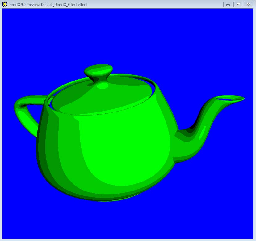
Figure 6.1 Toon shader we are going to implement in this chapter
Let's take a close look at Figure 6.1. How is it different from ordinary diffuse lighting? With diffuse lighting, the shading changes very smoothly across the surface, but, with toon shading, it changes suddenly after not changing for a while at all. In other words, it changes discretely as if you are walking down stair steps. Now, let's turn this observation into a graph for a better understanding.
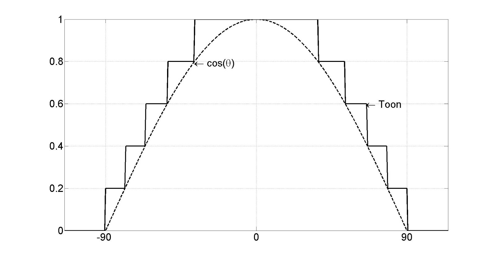
Figure 6.2 Difference between diffuse lighting and toon shading
It makes much more sense, right? No? Um, then how about a comparison table?
| Diffuse Lighting | Toon Shading |
|---|---|
| 0 | 0 |
| 0 ~ 0.2 | 0.2 |
| 0.2 ~ 0.4 | 0.4 |
| 0.4 ~ 0.6 | 0.6 |
| 0.6 ~ 0.8 | 0.8 |
| 0.8 ~ 1 | 1 |
Table 6.1 Comparison between diffuse lighting and toon shading
This table should give you a much better idea. Table 6.1 shows that we simply need to turn every range into its upper bound in order to convert diffuse lighting to toon shading. That sounds super easy, so let's go to RenderMonkey, right away!
Initial Step-by-Step Setup
After launching RenderMonkey, add a new DirectX effect and change the name from Default_DirectX_Effect to ToonShader. You see a matrix, named matViewProjection, right? Please delete it.
Figure 6.1 was showing a teapot model, which is often used in 3D graphics because its curvature is really good for demonstrating shader techniques. Therefore, we will use it in this chapter, as well. Inside RenderMonkey, find Model in Workspace panel. Then, right-click on it and select Change Model > Teapot.3ds.
To do toon shading, we should calculate diffuse lighting first, right? So, we need the light position and normal information as we did in Chapter 4. First, we will declare a variable for the light position. Right-click on ToonShader and select Add Variable > Float > Float4. A new variable will be added. Now change the name to gWorldLightPosition and set the value to (500, 500, -500, 1). Now, it's time to retrieve normal information from the vertex buffer. It is as simple as double-clicking on Stream Mapping and add NORMAL field. Make sure to set the data type to FLOAT3 and Index to 0.
Let's look at Figure 6.1, again. The teapot is green, right? There are different ways of coloring the teapot, but we will simply use a global variable to specify the color. Right-click on ToonShader and select Add Variable > Float > Float3. Once a new variable is added, change the name to gSurfaceColor. Now, double-click on the variable and change the value to (0, 1, 0). You haven't forgot that colors are represented as a percentage values between 0 and 1, right?
Now we are going to add some matrices. Until now, we always declared three separate matrices for world, view and projection matrices, but we will do something a bit different here to make things faster. If you concatenate all the matrices into one, you can just multiply the resulting matrix to a vector instead of multiplying the matrices separately. For example, we used to multiply world, view and project matrices to a vector in order. But we can just multiply these three matrices together to get another matrix, and multiply it to the vector to produce the same result. Performance-wise, this is faster because multiplying one matrix is faster than multiplying three.
For the reasons we just discussed, we will concatenate matrices here. Therefore, we only need one global variable to hold the concatenated matrix in the end. Right-click on ToonShader and select Add Variable > Matrix > Float(4x4). Then, change the variable name to gWorldViewProjectionMatrix, and right-click on it to select Variable Semantic > WorldViewProjection.
Multiplying a matrix only once sounds really great, but don't we still need a world matrix to calculate diffuse lighting? Light position is defined in the world space, so to find a light vector, we need a vertex position in the world space. It is the same story with the normal vector, as well. So yeah, passing a world matrix to do these multiplication twice is something we should do. But if you think a bit more, you can do the same thing with only one matrix multiplication.
The reason why we transformed the vertex position and normal vector into the world space was to match the spaces between all operands. You remember that the calculation is wrong if any of these is in a different space, right? The light position is already defined in the world space, so "why not transforming other information into the world?” was our logic. But here is another way. You can also transform the light position to the local space (of the object being drawn), while leaving the vertex position and normal vector unchanged in the local space. This also produces correct calculations since all the operands are in a same space. Even better, this way is faster because we transform only one vector instead of two.
Then how do we transform something from world to local space? Simply by multiplying the inverse matrix of world matrix. To add the inverse matrix to RenderMonkey, right-click on ToonShader and select Add Variable > Matrix > Float(4x4). Then, change the variable name to gInvWorldMatrix. Finally, right-click on the variable and select Variable Semantic > WorldInverse to finish all the setup!
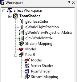
Figure 6.3 RenderMonkey project after the initial setup
Vertex Shader
I will show you the full source code first, and provide line-by-line explanation after.
struct VS_INPUT
{
    float4 mPosition : POSITION;
    float3 mNormal: NORMAL;
};

struct VS_OUTPUT
{
   float4 mPosition : POSITION;
   float3 mDiffuse : TEXCOORD1;
};

float4x4 gWorldViewProjectionMatrix;
float4x4 gInvWorldMatrix;

float4 gWorldLightPosition;

VS_OUTPUT vs_main( VS_INPUT Input )
{
   VS_OUTPUT Output;

   Output.mPosition = mul( Input.mPosition, gWorldViewProjectionMatrix );

   float3 objectLightPosition = mul( gWorldLightPosition, gInvWorldMatrix);
   float3 lightDir = normalize(Input.mPosition.xyz - objectLightPosition);

   Output.mDiffuse = dot(-lightDir, normalize(Input.mNormal));

   return( Output );
}
Input and Output Data of Vertex Shader
To calculate lighting, a normal vector is needed. So, the input structure will have vertex position and normal.
struct VS_INPUT
{
   float4 mPosition : POSITION;
   float3 mNormal: NORMAL;
};
The output structure is nothing special, either. The vertex shader will calculate diffuse lighting and pass the result to this structure. If you are not sure what I am talking about here, please review Chapter 4 again.
struct VS_OUTPUT
{
   float4 mPosition : POSITION;
   float3 mDiffuse : TEXCOORD1;
};
Now, declare three global variables explained earlier: two matrices and the light position.
float4x4 gWorldViewProjectionMatrix;
float4x4 gInvWorldMatrix;

float4 gWorldLightPosition;
I believe these were all the variables we added to RenderMonkey, so now you can move onto the vertex shader function.
Vertex Shader Function
First, we will perform the most important role of any vertex shader: transforming the vertex position to the projection space. Since world, view and projection matrices were merged into one already, this can be done with one line of code.
VS_OUTPUT vs_main( VS_INPUT Input )
{
   VS_OUTPUT Output;

   Output.mPosition = mul( Input.mPosition, gWorldViewProjectionMatrix );
Now, it's time to calculate diffuse lighting. As explained earlier, we will transform the light position to the local space to perform all the calculations in the local space.
float3 objectLightPosition = mul( gWorldLightPosition, gInvWorldMatrix);
Then, make a vector pointing from the light position to the current vertex position (in the local space.) Also don't forget to make the vector's length to 1.
float3 lightDir = normalize(Input.mPosition.xyz - objectLightPosition);
After the above code, the light and normal vectors are both in the local space, so we can calculate a dot product of these two to calculate diffuse lighting correctly.
Output.mDiffuse = dot(-lightDir, normalize(Input.mNormal));
Do you see that Input.mNormal is normalized here? Usually normalized normals are stored in a vertex buffer, but we are calling normalize() again just in case.
Now simply return Output.
   return( Output );
}
There was nothing hard with the vertex shader function because we already knew everything from Chapter 4. The only difference was that we used the local space in this chapter. But I believe it's not a hard idea to understand. Then, let's take a look at pixel shader.
Pixel Shader
As in Vertex Shader, I'll show you the full source code first.
float3 gSurfaceColor;

struct PS_INPUT
{
   float3 mDiffuse : TEXCOORD1;
};

float4 ps_main(PS_INPUT Input) : COLOR
{
   float3 diffuse = saturate(Input.mDiffuse);

   diffuse = ceil(diffuse * 5) / 5.0f;

   return float4( gSurfaceColor * diffuse.xyz, 1);
}
First, let's declare global variables and input structure of the pixel shader. The surface color is declared as a global variable, and the diffuse lighting, calculated in the vertex shader, is passed to PS_INPUT.
float3 gSurfaceColor;

struct PS_INPUT
{
   float3 mDiffuse : TEXCOORD1;
};
Now it's time to look at pixel shader function. First we clamp out meaningless negative values from mDiffuse.
float4 ps_main(PS_INPUT Input) : COLOR
{
   float3 diffuse = saturate(Input.mDiffuse);
Now we will divide diffuse into 5 discrete steps so that each step's width become 0.2. We can use ceil() function to do this. ceil() function ceils the input parameter to the nearest integer, but what we need is ceiling to the nearest multiple of 0.2. The following code solves our problem:
diffuse = ceil(diffuse * 5) / 5.0f;
Let's look at the above formula more closely. diffuse is between [0, 1], so multiplying 5 results in [0, 5]. When ceil() is applied here, the result will become one of these: 0, 1, 2, 3, 4 or 5. Now dividing the result by 5 will give us one of these values: 0, 0.2, 0.4, 0.6, 0.8 or 1. This is what we are looking for right? Figure 6.2 and Table 6.1 say so!
The last thing to do in pixel shader is multiplying the surface color as shown below.
   return float4( gSurfaceColor * diffuse.xyz, 1);
}
Now press F5 to compile vertex and pixel shaders separately and see the preview window. You will see a teapot as shown in Figure 6.1. What? The background color is different? Then right-click inside the preview window and select Clear Color to change it.
(Optional) DirectX Framework
This is an optional section for readers who want to use shaders in a C++ DirectX framework.
First, make a copy of the framework used in Chapter 3 and save it into a new folder. Then, we will save the shader and 3D model that we used in RenderMonkey so that they can be used in the DirectX Framework.
- From Workspace panel, find ToonShader and right-click on it. A pop-up menu will appear.* From the pop-up menu, select
Export>FX Exporter. - Browse to the folder we just created and save it as
ToonShader.fx. - From
Workspacepanel, findModeland right-click on it. A pop-up menu will appear. - From the pop-up menu, select
Save>Geometry Saver. - Browse to the folder we just created and save it as Teapot.x.
Now open the solution file in Visual C++.
First, we will find global variables we don't need anymore. Find all the instances of gpTextureMappingShader, and change them to gpToonShader. Also change all instances of gpSphere variable to gpTeapot. There's a texture variable, gpEarthDM, too. Since we don't use any texture in this chapter, please remove all instances of gpEarthDM variable from the code.
What new global variables did we add to shader? There were two: light position and surface color. Add the following code:
// Light Position
D3DXVECTOR4 gWorldLightPosition = D3DXVECTOR4(500.0f, 500.0f, -500.0f, 1.0f);

// Surface Color
D3DXVECTOR4 gSurfaceColor =       D3DXVECTOR4(0, 1, 0, 1);
We also set the same values used in RenderMonkey to above variables.
Now go to LoadAssets() function to change the name of model and shader to Toonshader.fx and Teapot.x, respectively.
bool LoadAssets()
{
    // loading textures

    // loading shaders
    gpToonShader = LoadShader("ToonShader.fx");
    if ( !gpToonShader )
    {
        return false;
    }

    // loading models
    gpTeapot = LoadModel("Teapot.x");
    if ( !gpTeapot )
    {
        return false;
    }

    return true;
}
Next is RenderScene(), which actually draws the scene. We need to pass two new matrices: a concatenated world/view/projection matrix and inverse of world matrix. First, to find the inverse matrix, add the following lines below the code calculating the world matrix.
    // find inverse matrix of the world matrix
    D3DXMATRIXA16 matInvWorld;
    D3DXMatrixTranspose(&matInvWorld, &matWorld);
D3DXMatrixTranspose() function used in above code finds the transpose matrix. The reason why we find the transpose matrix instead of the inverse matrix is because the world matrix is an orthogonal matrix. The inverse and transpose of an orthogonal matrix are same.
Now it's time to multiply world, view and projection matrices together. To do so, we use D3DXMatrixMultiply() function like this:
    // concatenate world/view/projection matrices
    D3DXMATRIXA16 matWorldView;
    D3DXMATRIXA16 matWorldViewProjection;
    D3DXMatrixMultiply(&matWorldView, &matWorld, &matView);
    D3DXMatrixMultiply(&matWorldViewProjection, &matWorldView, &matProjection);
Please note that the order of multiplication is World Matrix X View Matrix X Projection Matrix.
Now, we will pass these two matrices to shader. Delete all SetMatrix() function calls which were already in the code, and insert the following code, instead.
    // set shader global variables
    gpToonShader->SetMatrix("gWorldViewProjectionMatrix",
        &matWorldViewProjection);
    gpToonShader->SetMatrix("gInvWorldMatrix", &matInvWorld);
Finally, don't forget to pass the light position and the surface color.
    gpToonShader->SetVector("gWorldLightPosition", &gWorldLightPosition);
    gpToonShader->SetVector("gSurfaceColor", &gSurfaceColor);
If you compile and execute the program, you will see a spinning teapot. With rotation, you should be able to see the toon shader effect much better, especially on the spout and handle.
Summary
A quick summary of what we learned in this chapter:
- Toon shader is one of the non-realistic rendering techniques.
- Toon shader is nothing more than changing diffuse shading, which is continuous, to discrete.
- Vector transformation can be optimized with matrix concatenation.